Overview
Interactive installations combine physical elements with digital technology to engage users in a space. They typically consist of a loop: input collects data, a processor runs logic, and the output responds. Over time, I’ve found that planning these systems carefully requires a clear signal-flow framework that breaks down every connection. Mapping the entire chain upfront makes it possible to design even complex installations in a clear, step-by-step way.
The goal is a confident, modular approach: define each part of the system before building it.
System Framework
At the core is an expanded Input → Process → Output model. I recommend visualizing each project as a labeled signal-flow diagram, showing every component [Hardware Component (Role: Details)] and connection (Interface: Protocol). For example:
[Button (Input)] --> (Wire) --> [Arduino Uno (Processor: Arduino IDE, C++)] --> (Wire) --> [LED (Output)]This diagram reads as: a button sensor sends a digital signal to an Arduino, which then drives an LED output. Drawing systems this way forces every link to be explicit — USB, HDMI, I²C, Wi-Fi, and so on. I refer to this approach as an I/O Signal Flow Diagram, and it’s the foundation of the Interactive Design Guide.
Components
Interactive installations can be broken into three main parts:
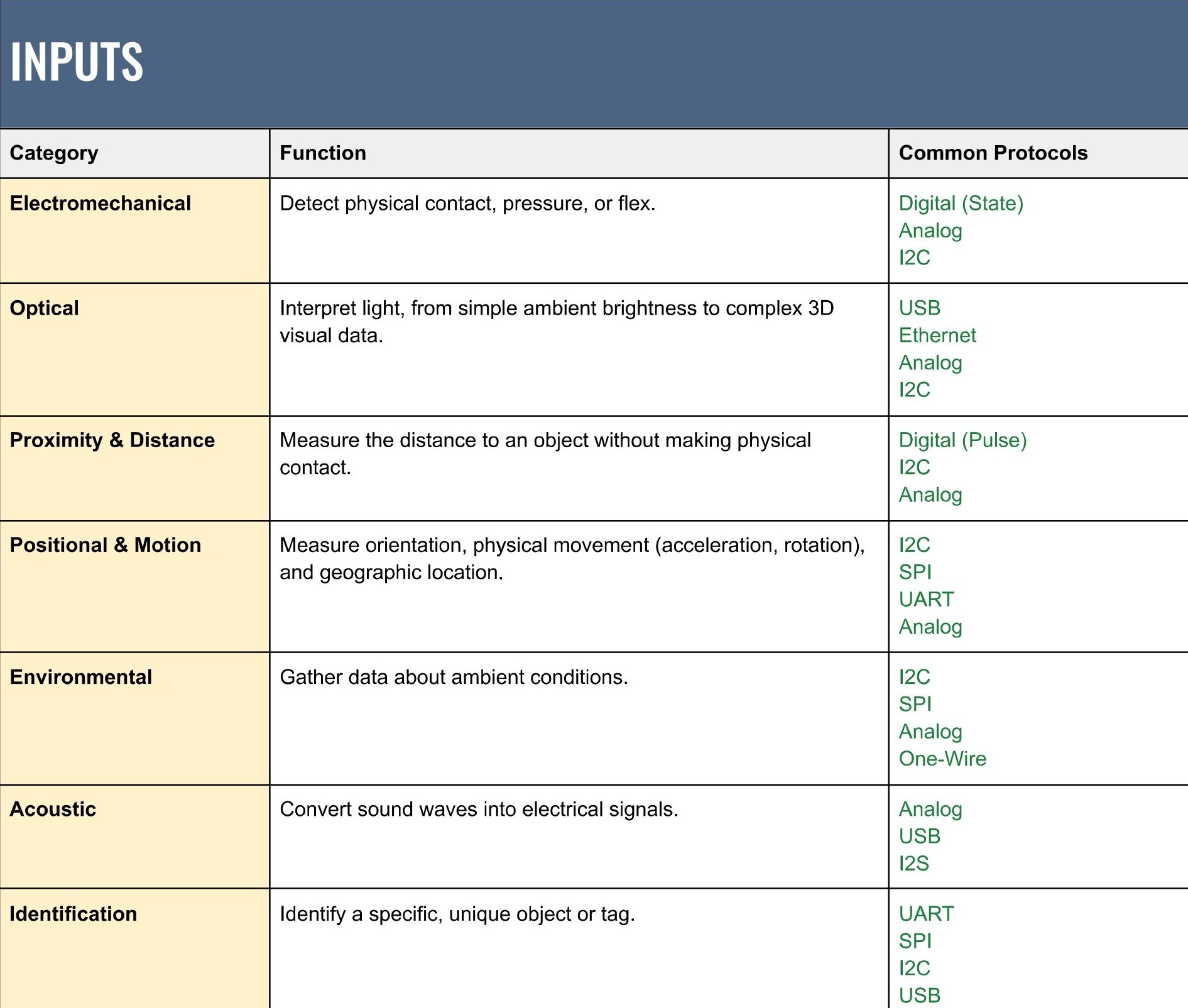
- Inputs (Sensors): Devices that sense the environment, such as cameras, touch panels, microphones, or proximity sensors. They convert physical phenomena into data the system can read. Different inputs create very different kinds of interaction, so the choice here has a big impact on the experience.
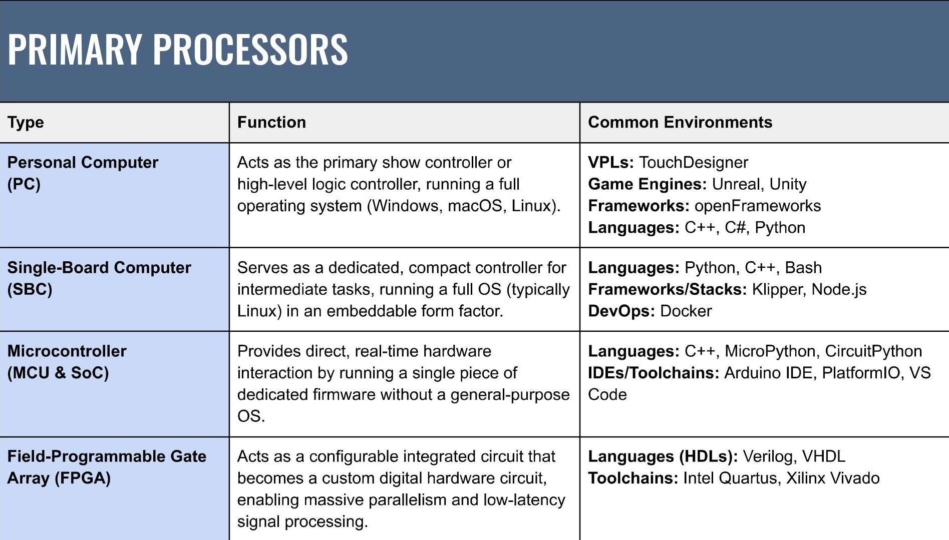
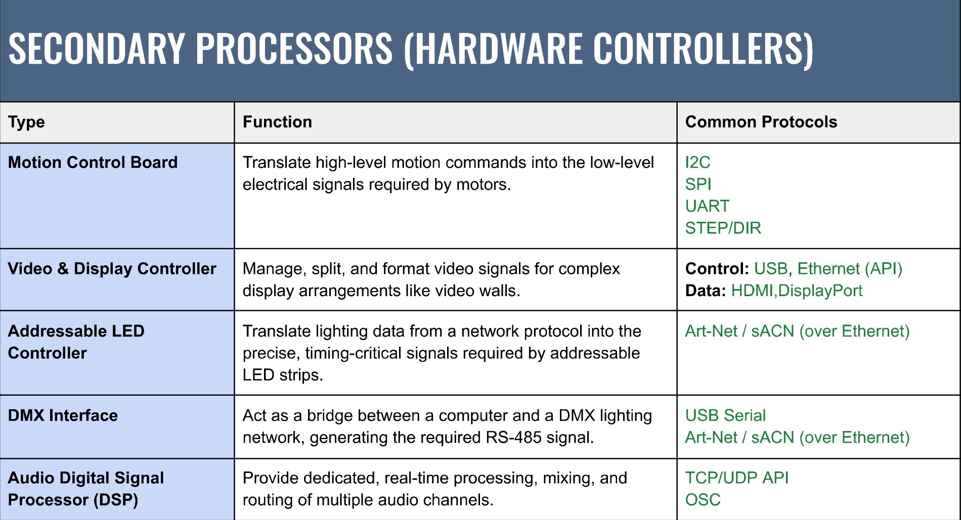
- Processors (computer or microcontroller): The brains of the system. This might be a PC running creative software (TouchDesigner, Max/MSP), a microcontroller (Arduino, ESP32), a single-board computer (Raspberry Pi), or a combination. I often split responsibilities across processors so no single device is overloaded and debugging stays manageable.
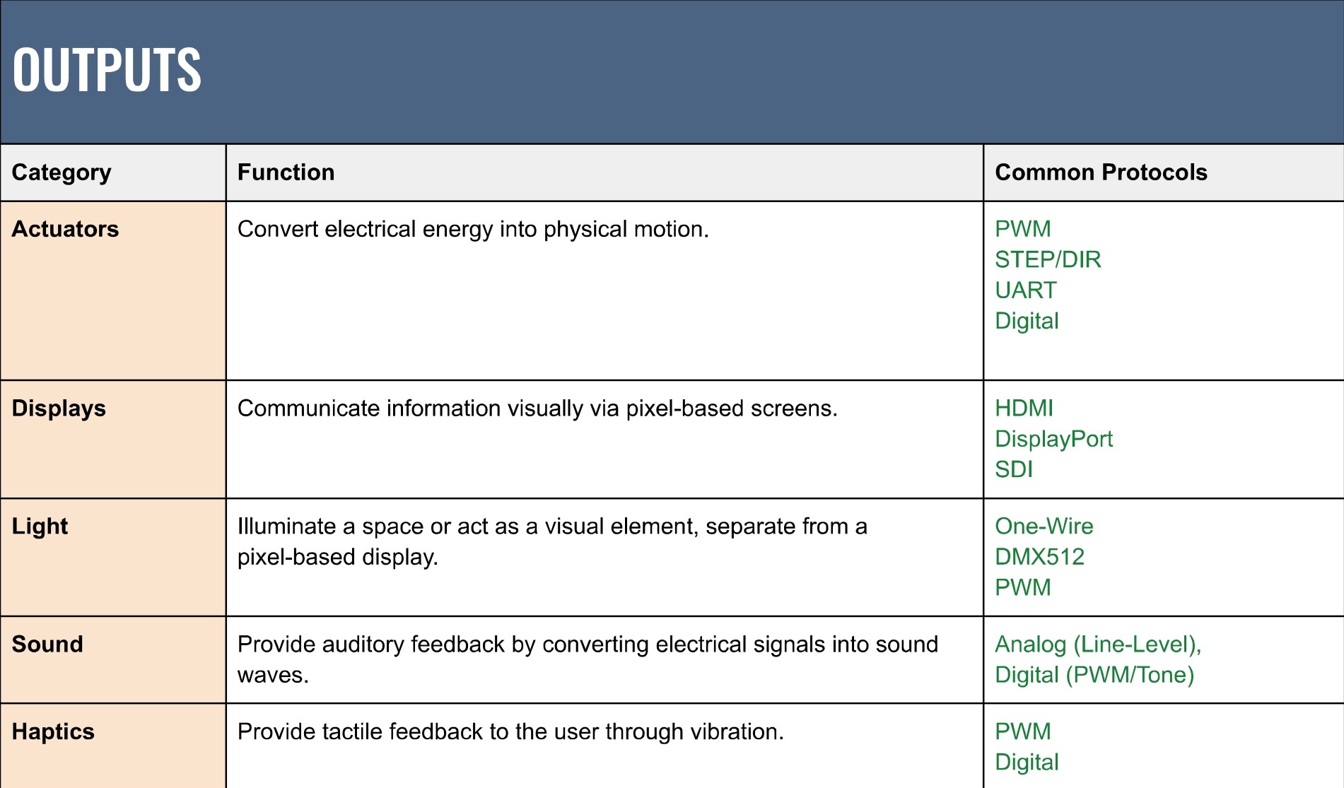
- Outputs (Displays / Actuators): How the system responds. Screens and projectors handle visuals; speakers handle sound; motors and actuators introduce physical motion. Some outputs — especially mechanical ones — require feedback and safety considerations, which should be designed into the system early.
Each component connects via a specific interface. Planning inputs, processors, outputs, and their protocols together helps avoid surprises later in the build. A touch overlay might connect via USB, a computer to displays via HDMI, and a microcontroller to motors via I²C or PWM.
Protocols & Interfaces
Protocols can be broken into four layers — each one answers a different design question about range, latency, and reliability.
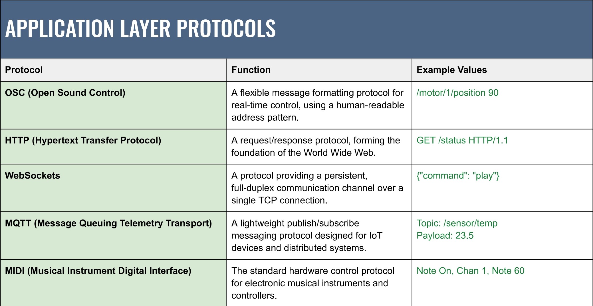
- Application (software ↔ software): Human-readable control and messaging between programs — e.g.
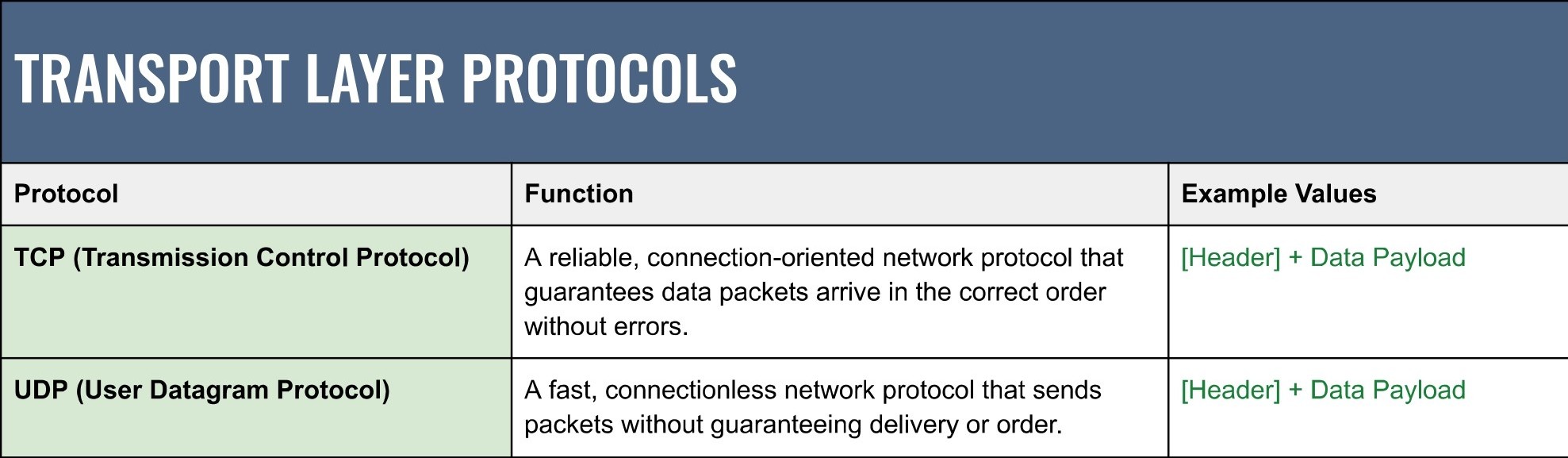
OSC,WebSockets,HTTP,MQTT. Use these for animation parameters, dashboards, and remote APIs. - Transport (network transport): The packet carriers —
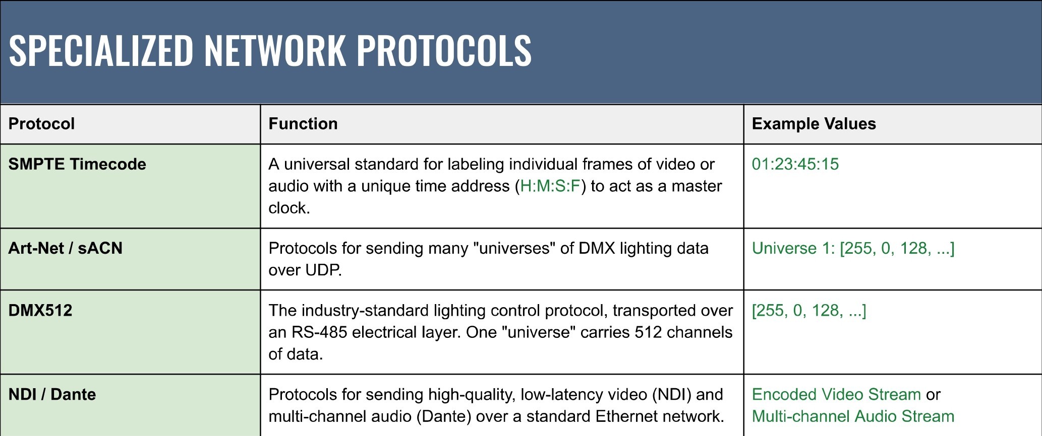
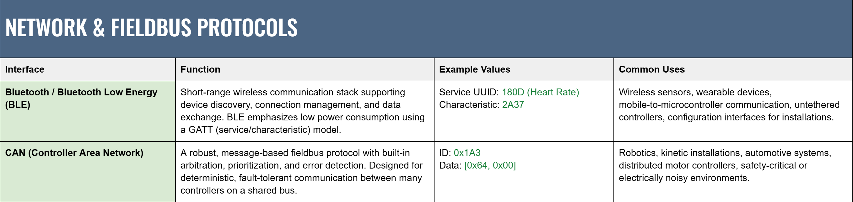
UDP(low latency, lossy) andTCP(reliable, ordered). Pick UDP when recent realtime data matters more than perfect delivery. - Network & Fieldbus (wireless / wired device networks): Protocol stacks that manage device addressing and arbitration — e.g. Bluetooth / BLE (short-range, low-power GATT profiles), CAN (robust, deterministic fieldbus), and AV-specific network protocols like
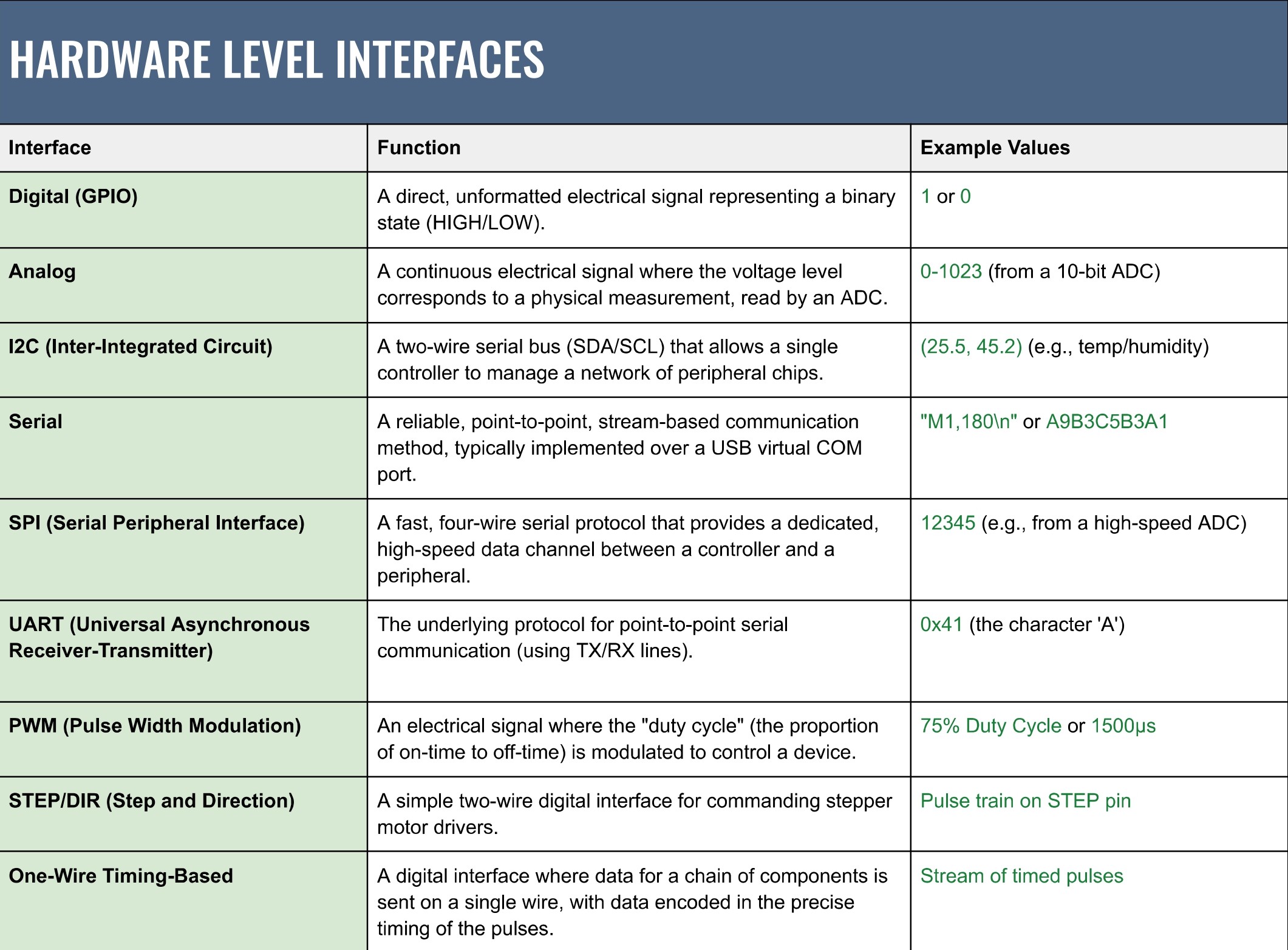
Art-Net/sACN. Use these when devices share a bus or need industrial-grade robustness. - Hardware-level interfaces: Chip-to-chip and pin-level links:
I²C,SPI,UART/Serial,PWM,GPIO,One-wire (timing)for addressable LEDs, andSTEP/DIRfor steppers. These handle the lowest-latency, electrical connections inside enclosures. Documenting the chosen protocols in the I/O signal-flow diagram can save hours of debugging and future maintenance.
Downloadable Guide
Interactive installations are easier to design and maintain when their systems are clear, modular, and adaptable. Breaking a project into inputs, processors, outputs, and protocols provides a mental model that scales with complexity. The I/O Signal Flow Diagram turns abstract ideas into concrete plans and exposes integration decisions early, when they’re easiest to change.
For a deeper dive, the Interactive Design Guide expands on these concepts with additional diagrams, system patterns, and deployment considerations. It’s intended as a practical reference for moving from early sketches to reliable, real-world installations.